Overview

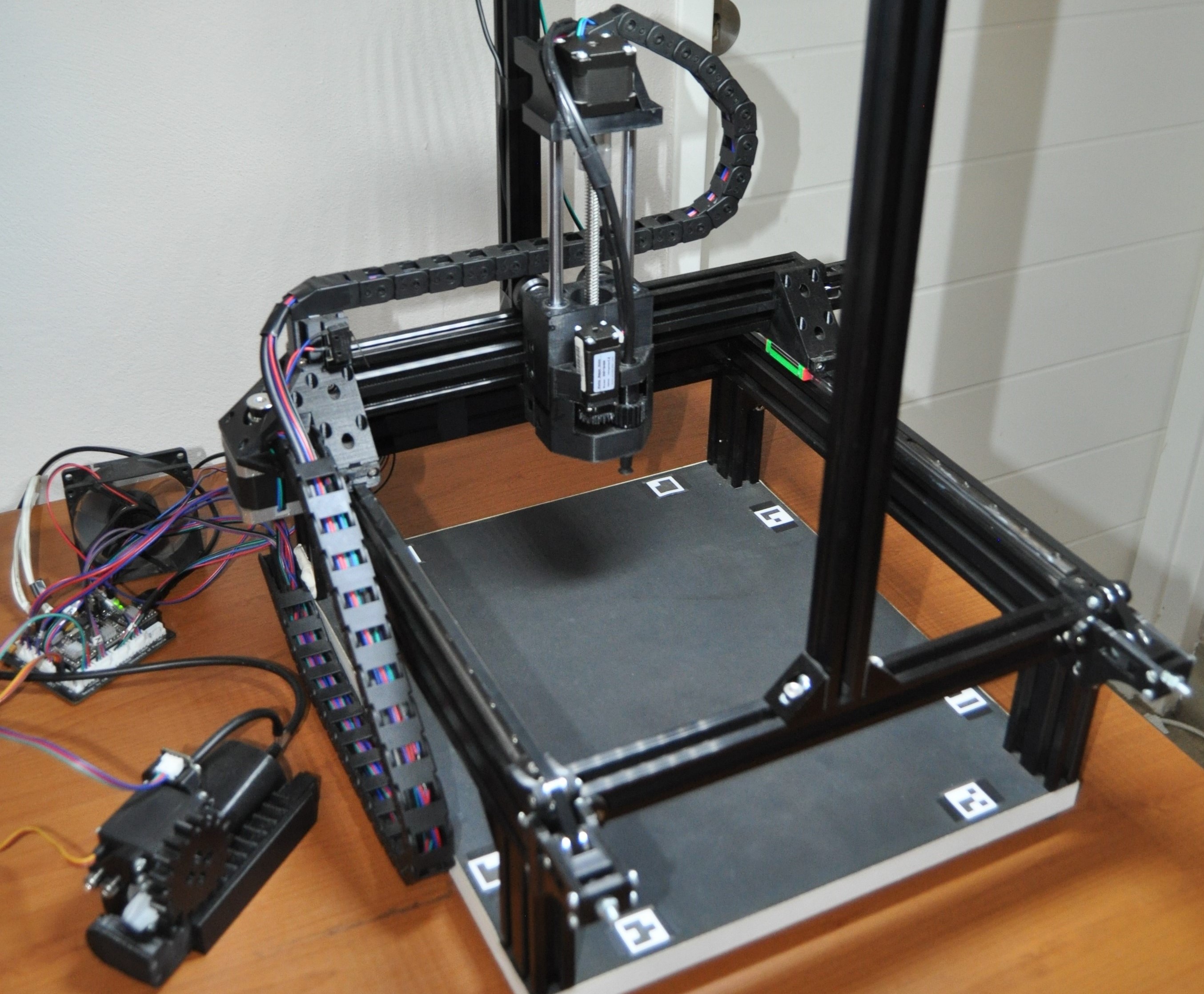
The primary goal of the system is to stack small aluminum cubes (with side length 13mm / 0.5in) to form arbitrary shapes defined by the user. In order to move, rotate and place the cubes, a robotic subsystem was developed which consisted of both a mechanical component and an embedded circuit component. The secondary system goal is to complete the shape construction in a robust manner. This requires the system to be able to detect if a cube is accidentally dropped during construction, find the cube and continue construction. Furthermore, it also required that the system is able to detect when there is damage to the shape under construction. A computer vision system was developed in support of these goals. A computer software program with a GUI was developed to facilitate control of the robot, monitoring of the construction process and insight into the computer vision system. Additionally, the software also included a 3D design tool to allow the user to design the shapes to construct. All system components were developed from first principles.

Construction of 2D Pyramid

Timelapse of the robot constructing a sparsely stacked 2D pyramid with cubes in alternating rows rotated by 45 degrees.

Construction of 3D Pyramid

Timelapse of the robot a 3D pyramid with alternating planes rotated by 45 degrees.

Response to Dropped Cube

Capability of the system to detect when a cube is dropped during construction as well as to pick up the cube and continue construction. It is shown from the perspective of the video feed in the user software.

Detection of Construction Failure

Capability of the system to detect a construction failure when stacking the cubes from the perspective of the video feed in the user software.

Mechanical Design of Robot

The purpose of the robot is to move and rotate the cubes such that they can be stacked in arbitrary shapes. A Cartesian gantry robot with 4 degrees of freedom was designed and constructed to achieve this. The robot is capable of moving the cube linearly in 3 dimensions and rotating it about its vertical axis. The robot was constrcuted using machined aluminum parts, custom PETG 3D-printed parts and various store bought components. The robot grips the cubes using a suction cup mechanism. The suction is generated using a syringe connected to the suction cup using a tube and a servo motor in conjunction with a rack and pinion is used to extend and retract the syringe plunger.

Embedded Controller

An embedded controller is required to act as an interface between the user software and the robot. The controller converts movement and action instructions sent to the robot into control signals for the robot's motors and suction system actuator. In addition, the embedded controller collects information from the robot's position and suction system pressure sensors to send back to the user software. The embedded controller is based around a STM32 microcontroller which was programmed using C. No libraries were used for the firmware and all drivers were developed from first principles at the register-level. The complete circuit was first prototyped on a breadboard before KiCAD was used to design and develop the final PCB. All components were hand-soldered onto the PCB.

Computer Vision System

In order to ensure robust operation, the robot needs to be able to locate any dropped cubes to pick them up and needs to be able to analyze the shape to identify any construction defects. The computer vision system was developed for this purpose. The system made use of a singular monocular camera mounted above the robot's workspace to gather the necessary visual data. A number of fiducials were placed in known positions in the robot's workspace to allow the vision system to localize the workspace with respect to the camera's position. Using this in conjunction the pinhole camera model and some known properties about the cubes allows the vision system to compute the position and orientation of all cubes in 3D space. The system compares this to an internal model of the expected cube positions to identify and correct any anomalies that arise during construction. All the computer vision algorithms were implemented from first principles using C++ in conjunction with OpenCV for image data management.

User Software

A computer software program is required to provide the user with an interface to the system. The user software fufils a number of functions. Firstly, the software allows the user to design an arbitrary shape to be constructed by virtually placing 3D cubes with a design tool which was implemented from first principles using OpenGL. The software also includes funcitonality to connect to and control the robot directly or to initiate the construction of a designed shape by the robot using real cubes. During construction, the interface shows a live feed from the camera with the option to view various stages of the computer vision pipeline applied to the feed. In addition, the interface also shows the live 3D model of the known position and orientation of all cubes in robot's workspace. The user software was developed using C++ in conjunction with the QT framework.

The video below shows the user software used to design the shape to be constructed and initiate construction. The software also shows information from the computer vision system and model of the cube positions during the construction process.